Shielded cables and connection systems with EMC protection in industrial applications
Why is EMC protection important?
Nowadays it’s difficult to find or create a product or industrial plant without modern cabling technology. Industry 4.0, Big Data and fully automated processes are on everybody’s lips.
Parts of these processes are managed or controlled by frequency converters, transformers, electrical switches and communication devices.
However, these kinds of switching processes always involve the risk of interference. Precision and the selection of the right components are needed to keep the machine running perfectly.
The aim is for all processes to function smoothly and without errors. This is because something that’s just a bit disruptive like interference on the radio can have far more dramatic consequences in the context of medical technology if the system fails.
This is why industrial environments need ever greater safety against electromagnetic interference. Electromagnetic compatibility (EMC).
How does EMC work?
An electromagnetic interference always originates from an interference source. This can be an item of equipment that carries a high current, such as a frequency controlled motor or a cable.
The source of interference corresponds to a disrupted piece of equipment, known as the interference sink. The interference sink can be a sensor or data network cable, for example.
The coupling mechanism in between causes the interference. This can be divided into four different types of coupling :

- Conductive coupling
The interference source and interference sink are linked with one another, for example by means of a common earthing conductor. An interference current via the common earthing conductor causes electromagnetic interference. - Capacitive coupling
The interference source and interference sink are close to one another, but not physically connected. With capacitive coupling, the electromagnetic interference (EMI) is produced by the electric field. - Inductive coupling
With inductive coupling, the interference source and interference sink are also close to each other, but are not connected to one another. However, the interference is caused by the magnetic field. - Radiative coupling
Radiation coupling generally occurs when the interference source and interference sink are far apart and the conductors ultimately act as antennae and cause the interference from electromagnetic radiation.
In practice, this is usually a mixture of these 4 coupling mechanisms, which must be eliminated, for example by using screened cables.
What is the EMC directive?
In EMC Directive 2014/30/EU, Article 3, electromagnetic compatibility is defined as:
"[...] the ability of a piece of equipment to operate satisfactorily in its electromagnetic environment without causing electromagnetic interference, which would be unacceptable for other equipment in this environment."
According to this definition, EMC has two main aspects:
- The equipment must not cause electromagnetic interference.
- The equipment must not be electromagnetically disrupted by its surroundings.
For an EMC-compliant design of your data communication we recommend the EMC directive of the PNO.
How is EMC protection measured?
EMC protection is measured and stated using coupling resistance [mΩ/m] and/or screening attenuation [dB]. The coupling resistance of cables and wires is normally specified at a defined frequency of 30 MHz. By contrast, screening attenuation is used for high frequencies from 50 MHz.
Coupling resistance and screening attenuation cannot be calculated. This means that the values can only be determined using measurements. The triaxial measuring tube method defined in EN 50289-1-6 is used to determine the values.
What does the EMC law mean for cables, connectors and cable glands?
LAPP offers you cables, connectors and cable glands, among other things. According to the definition of the German Electromagnetic Compatibility of Equipment Act, these are “components without a direct function”. These components are not covered by the EMC Directive 2014/30/EU and therefore do not have the CE marking with reference to the EMC Directive.
The CE markings that you still find on LAPP products refer to the verification of CE conformity in accordance with the Low Voltage Directive, RoHS and CPR CE, amongst other things.
Normative requirements for EMC protection of cables, connectors and cable glands
Cables, connectors and cable glands are thus mentioned very little in the EMC Directive. This means that special, normative EMC requirements often apply to these components, for instance those from the design standard DIN EN 50525-2-51:2012.
This standard requires proof of compliance with a minimum efficiency of the copper braiding for the screened version of cables. This efficiency is illustrated by the above-mentioned coupling resistance.
The screened versions are designated as H05VVC4V5-K as standard. The cables for this in the Lapp cable range are:
TIP: In the article search, you can find all screened cable versions with the standard designation "H05VVC4V5-K".
When should screened cables be used?
Wherever electric motors, switches and cables are used for energy transmission, these cause electromagnetic interference. EMI can have a negative influence on data cables, sensors and similar equipment.
In other words, this means that you should rely on power and control cables or data cables with electromagnetic protection through screening in all these areas that are susceptible to interference.
How are screened power and control cables constructed?
There are four different screening types for power and control cables. Three of these shields are particularly suited to use with EMC protection :
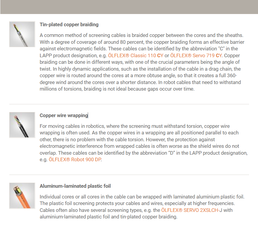
- Tin-plated copper braiding
A common method of screening cables is braided copper between the cores and the sheaths. With a degree of coverage of around 80 percent, the copper braiding forms an effective barrier against electromagnetic fields. These cables can be identified by the abbreviation "C" in the LAPP product designation, e.g. ÖLFLEX® Classic 110 CY or ÖLFLEX® Servo 719 CY. opper braiding can be done in different ways, with one of the crucial parameters being the angle of twist. In highly dynamic applications, such as the installation of the cable in a drag chain, the copper wire is routed around the cores at a more obtuse angle, so that it creates a full 360-degree wind around the cores over a shorter distance. In robot cables that need to withstand millions of torsions, braiding is not ideal because gaps occur over time. - Copper wire wrapping
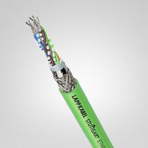
For moving cables in robotics, where the screening must withstand torsion, copper wire wrapping is often used. As the copper wires in a wrapping are all positioned parallel to each other, there is no problem with the cable torsion. However, the protection against electromagnetic interference from wrapped cables is often worse as the shield wires do not overlap. These cables can be identified by the abbreviation “D” in the LAPP product designation, e.g. ÖLFLEX® Robot 900 DP. - Aluminum-laminated plastic foil
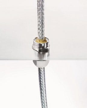
Individual cores or all cores in the cable can be wrapped with laminated aluminium plastic foil. The plastic foil screening protects your cables and wires, especially at higher frequencies. Cables often also have several screening types, e.g. the ÖLFLEX® SERVO 2XSLCH-J with aluminium-laminated plastic foil and tin-plated copper braiding.
How are screened data cables constructed?
Data cables have essentially the same screening as power and control cables, but other abbreviations are common in product designations:
Tin-plated copper braiding „S“ (Screened)
Aluminium-laminated plastic foil „F“ (Foiled)
There are also two special features for data cables in terms of their screening rating for EMC protection:
- Unscreened
Data transmissions are particularly susceptible to interference, which is why data cables are generally always screened. For certain areas of application for signal transmission, there are unscreened data cables specially marked with the abbreviation “U” (unscreened), such as the Cat.6 network cable ETHERLINE® LAN Cat.6 U/UTP 4x2xAWG24 LSZH, the Cat.5e Ethernet cable ETHERLINE® LAN Cat.5e SF/UTP 4x2xAWG24 or our UNITRONIC® BUS ASI cables for networking systems in the field. - Twisted Pair
Another design for data cables is twisted pair cables. Individual data pairs are twisted here. The twisting ensures that field effects compensate each other. These cables can be identified by the abbreviation “TP” (Twisted Pair). For instance, the ETHERLINE Cat 6a H 4x2xAWG22/1 SF/UTP cable is divided up as follows: ScreenedFoiled/UnscreenedTwistedPair. This network cable is screened around all cores with a wire braid and an aluminium-laminated plastic foil underneath (screened/foiled). The core pairs are twisted in pairs and are not equipped with additional core pair screening (UnscreenedTwistedPair).
How can cables and wires be connected in accordance with EMC?
Did you know that screening has no effect if it is not earthed? The electrical resistance between the cable screen and earth potential must be as low as possible. For this, the contact area must be as large as possible. If the connection between the shield and the EMC component is made correctly and, above all, over as large an area as possible, it generates no or only very low impedances even over long distances. The essential advantage: Your connection is thus particularly electromagnetically compatible.
The requirements at a glance :
- The copper shielding braid is laid out all around (over a large area) and without gaps at the transition into the enclosure.
- The cable gland is connected to the metallic enclosure wall with low impedance.
- The assembly and disassembly of the cable must be possible quickly, easily and without damage to the copper shielding braid.
- Optimum shield contact is ensured at both ends of the cable and applied to the earth potential.
A common method is to apply the shield all around and without gaps, e.g. at the transition from the cable gland to the connector or when introducing the cable into an enclosure by means of an EMC gland.
Only then can the connection act as a Faraday cage and reliably keep out interference signals from outside. It is also important that this optimum shield contacting takes place at both ends of the cable and is connected to the ground potential.
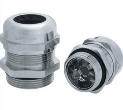
The SKINTOP® series cable glands are better suited for flexible cable diameters.
At LAPP, we offer you these in two types. Both are characterized by quick and easy assembly and a large clamping range. The cable is centered, fixed, strain relieved and hermetically sealed in a single operation.
The flexible EMC contact spring creates a highly conductive, low-resistance contact with the cable screen in the SKINTOP® MS-SC-M.
Because our SKINTOP® BRUSH series is especially suitable for flexible cable diameters. The products enable you to install them quickly and easily while at the same time providing a high clamping range for your copper shielding braid.
Your advantages at a glance :
- Thousands of ring-shaped brush hairs reliably protect your data streams from induced interference signals from outside.
- A large, variable clamping range makes assembly and disassembly easier and faster.
- The cable is centred, fixed, strain-relieved and hermetically sealed in one step.
Why are connectors important for EMC protection?
Every system is only as good as its weakest point. LAPP connector systems have the advantage of using all the aforementioned screening connection concepts. Very often, EMC cable glands are already integrated into the connector, offer the option of connecting a protective hose and enable the cable screening to be contacted with the working or PE contact of the connector system.
The standard housing is powder-coated with a non-conductive seal between the housing parts, which insulates them from one another. EPIC® EMC connectors offer 360-degree screening and vibration-proof screening connection. The EMC connectors can be identified by their metallically conductive, usually nickel-plated surface. The seals are designed to ensure that the two housing parts pressed or screwed together are in low-resistance contact with metal on metal. The same principle applies to both cable glands and the mounting wall.
Rectangular connectors feature an integrated SKINTOP® MS-M BRUSH cable gland. Der EPIC® ULTRA H-A3 and EPIC® ULTRA H-B6-24 are therefore easy to assemble and designed for a wide cable clamping range in screened cables.
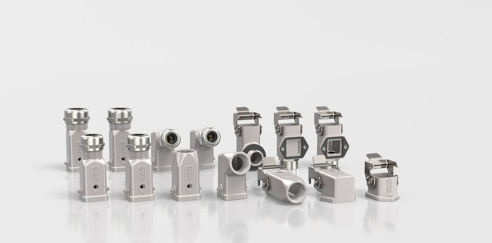
EPIC® ULTRA connectors
If you need a space-saving design, for example for use in servo drives, actuators and sensors, we recommend the POWER and SIGNAL circular connectors from LAPP. These are equipped with a specially coordinated EMC cable gland for servo and data cables.
EPIC® POWER M17, EPIC® POWER LS1, EPIC® POWER LS1.5 or EPIC® POWER LS3 circular connectors with integrated EMC cable gland are particularly suited to vibration-proof connections for power supply.
For example, LAPP offers EPIC® SIGNAL M17 or EPIC® SIGNAL M23 connectors for sensor, fieldbus, resolver and encoder cables.
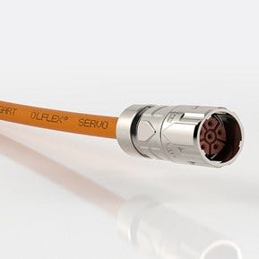
EPIC® POWER LS1 SPEEDFLEX circular connector
How can unscreened cables and cables be screened afterwards?
If an unscreened cable is not possible in the system for various reasons, or if cables only need to be electromagnetically screened in certain sections of the system, the LAPP protective conduits can also be equipped with our SILVYN ® conduits as well with copper braids or wrapped in the 3M Scotch 1183 screening tape.
For these systems, LAPP offers a one- and two-part screening connection for connecting the copper braiding to a housing wall or a connection contact for looping through the cable shield.
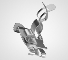
Our EMC-Guard shield clamp for reliable grounding of cable shields / shield grounding: Especially when there is a lack of space in control cabinets as well as on motor controls, housings or machine installations, stripped, shielded cables can be mounted quickly and without tools using our EMC-Guard shield clamp.
The stripped cable is pressed into the shield clamp and contacted consistently by the spring. This enables a permanent contact of shielded cables with ground potential and a reliable discharge of interference currents.
In addition to large-area shield contacting, it ensures space-saving installation with different clamping areas and is suitable in the "DINrail" variants for DIN rail mounting or "MOUNT" for direct mounting on e.g. mounting plates using an M4 screw.
How can EMC protection be improved?
To ensure optimum screening, cables can be fitted with double screening or installed in a copper or steel pipe. From an EMC perspective, these screens are completely sealed. LAPP SILVYN® offers you the optimum EMC protection. The EMC AS-CU protective conduit from the SILVYN® product brand is a metal protective conduit with copper braiding and is therefore suitable for particularly harsh environments with high electromagnetic requirements. The SILVYN® MSK-M BRUSH conduit gland with EMC protection and integrated strain relief rounds out your EMC-screened system.
Are there pre-assembled power, control and data cables with EMC screening?
Poor EMC is often the cause of installation errors. For a long time, it was customary in industry to buy cables and plugs separately and only connect them when installing them in a machine or production plant, for example.
There are a few disadvantages to greater flexibility: processing quality often leaves a lot to be desired. For instance, if the installer cuts too deep when stripping and damages the core insulation or only partially connects the screening to the housing of the plug, causing EMC problems.
This is why the trend is towards ready-assembled cables, which we at LAPP sell under the name ÖLFLEX® CONNECT. The cable and plug are already connected ex works. Customers even receive drag chains fully equipped with cables and hoses, and LAPP also takes over the engineering work. Customers are therefore guaranteed to always receive optimal quality from a single source and can also concentrate on their own work, namely building machinery.